V Phase Wiring Diagram
V Phase Wiring Diagram. A wiring diagram is a schematic which uses abstract pictorial symbols to show each of the interconnections of components in a very system. Use the top diagram to help.

Wiring Diagram of Single Tube Light Installation with Electromagnetic Ballast.
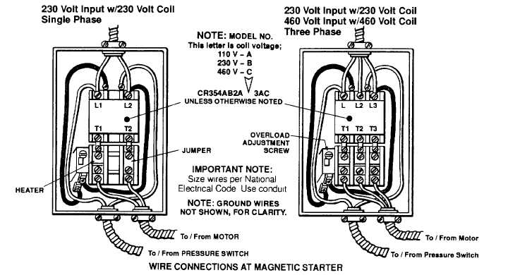
C. electrical If starter is used on lower voltage, connect per coil diagram.

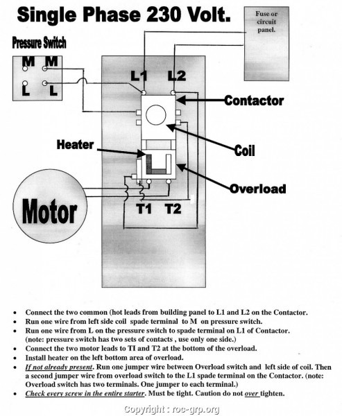
Single Phase Motor Wiring Diagram With Capacitor Start ...
[DIAGRAM] Single Phase 240v Transformer Diagram FULL ...
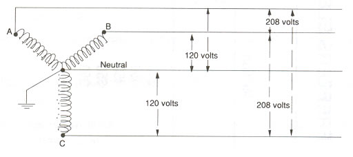
What's the difference between a 120 volt and 120/208 volt ...
Gould Century Motor 5hp 240 Single Phase Wiring Diagram
240V Transformer Wiring Diagram - Wiring Forums

220 Volt 3 Phase Wiring Diagram

[DIAGRAM] High Voltage Motor Wiring Diagram FULL Version ...
120 208v Single Phase
208V Single Phase Wiring Diagram - Wiring Diagram And ...
It shows how the electrical wires are interconnected and can also show where fixtures and components may be connected to the system. Diagrams are provided for both single and three-phase circuits, and are readily identified in the Selection Table on the following page. For all other SINGLE-PHASE wiring diagrams refer to the manufacturers data on the motor.

0 Response to "V Phase Wiring Diagram"
Post a Comment